PLEASE USE THE YMFC-AL (AUTO-LEVEL) SOFTWARE: https://youtu.be/DYpHB-LfloI
These videos are just for reference. The new software is much easier to setup and supports almost all transmitters.
You can download the Arduino sketch here:
http://www.brokking.net/ymfc-al_main.html




![Runcam DVR × Cygnet2[FPV094] Runcam DVR × Cygnet2[FPV094]](https://quadcoptersource.tesb1.com/wp-content/uploads/2019/12/Runcam-DVR-Cygnet2FPV094-200x137.jpg)
I still do not understand what the complementary is doing or why it is needing, how does it reduce noise?
look at mine i did what you said but i got this:
what do you think
sketch, PID Arduino
Make an Excel document and add some data. Filter it with an complementary filter and see what it does.
Hey Joop, superb video! I wanted to bring something to your attention about the Arduino servo library. In your videos you went to a great trouble in order to make the refresh rates of the Arduino faster for the ESCs, hence better PID control, but I found that
with one single change to the Servo header file, you can have the Arduino servo library refreshing at the interval you want. You
may do this by changing the #REFRESH_INTERVAL value. Simply copy the file to the desktop, change the value, and copy the file back to the servo folder. I am going to check this out with an oscilloscope tomorrow.
Just wanted to let you know for less headache in the future
When ever i set an ‘I’ value for the PID one or two of the props will start to increase its speed and flip the copter even when all sticks on the transmitter arent moved. Anyway to solve this
Double check everything because there is something wrong with your setup and/or hardware. Test the quadcopter in your hand and you will feel that it is correcting in the wrong direction. Make sure all the motors rotate in the correct direction and that the props are not reversed. Also check the connections of the ESC’s and rerun the setup.
Joop Brokking thank you for your response, everything is working correctly when calibrating the PID until I attempted to add any sort of value on I and D and P are working because I can feel it while it’s in my hand
If you used the same hardware as I did in the video the quadcopter should fly with the stock settings.
Joop Brokking I did try stock settings but same result but putting 0 on the I gain stops the problem. could it be a problem with my transmitter?
If all the checks with the ESC calibration program work without problems and you get the same results as I did in the video the quadcopter should not flip.
The quadcopter will only flip if there is a hardware problem. And this is something you need to track down yourself. Do you have a link to a picture so I can have a look?
Hello – I like your video and the site. Well done! I am still waiting for my QC parts to come, so going over good videos in the meantime. I have a question, what is the difference between the code you have explained and the multiwii platform software. Do both these have same objective? Also, if I plan to use GPS, what modifications are needed?
Finally, despite many searches, I was not able to find any good demonstration / code for follow-me GPS or being able to fly Quadcopter on specific Lat/Long coordinates or auto come home feature. Any pointers?
many thanks – eric
Great video Sir Joop. please I wish to know ,Where is the receiver signal from ?? I’m currently working on a wind pendulum project and I hope to adopt your PID lesson to balance the pendulum at center within the shortest time given , the pendulum has 4dc fans attached to its 4sides .how can I apply your lesson? Thanks for your help in advance
Don’t know if this has been pointed out yet, but at 3:32 there is a typo in the Derivative term, it should be:
D-output = (gyro – receiver – gyro_prev *+* receiver_prev) x D-gain
Great video, anyway!
Great spotting It should actually be:
D output = ((Gyro – Receiver) – (Gyro Prev- Receiver Prev) ) * D gain
Hi Joop,
in PID controller, i see pid_i_gain_roll = 0.04;
when i start quadcoptor , pid_i_mem_pitch increase very fast.
So that, quadcoptor make somersaults
can i decrease pid_i_gain_roll = 0.02. it ok?
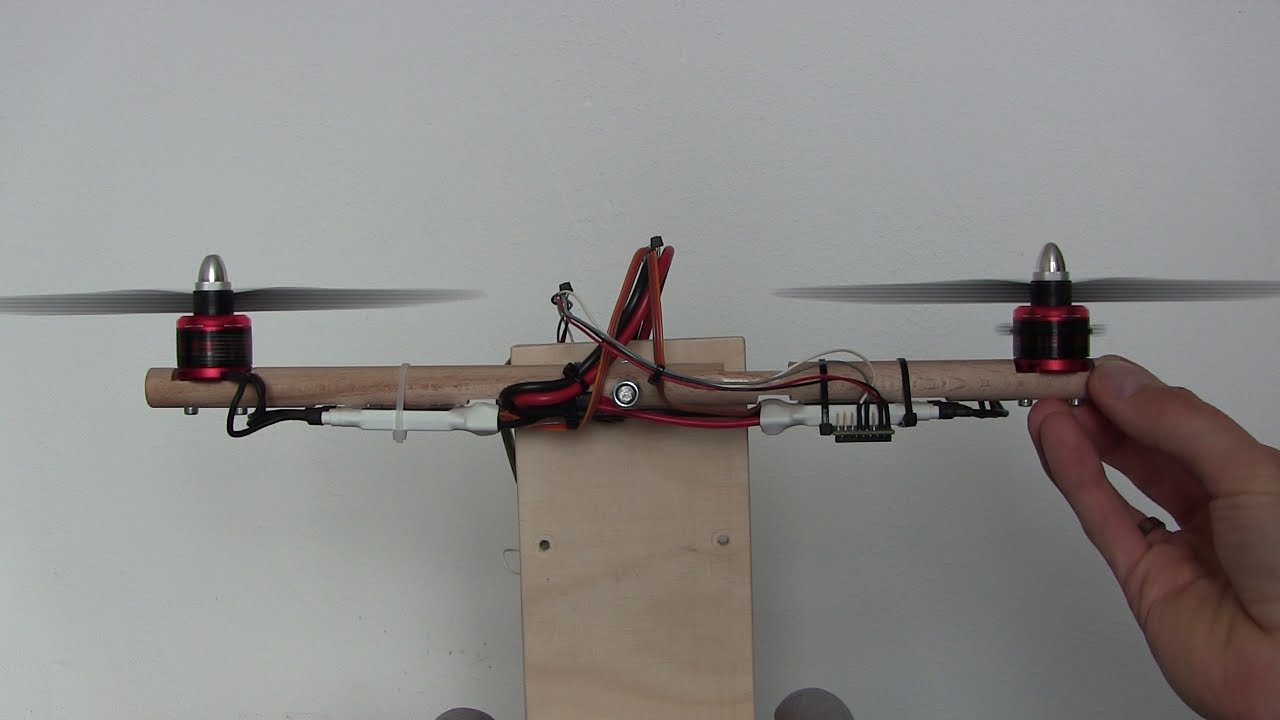
That will not help. Test the quadcopter in your hand as shown in this video:
If you test the quadcopter on the ground it cannot correct itself and the i-mem will increase fast.
Verry good thanks great work.thanks for sharing big help
Hi my friend is the stock PID Values are mede for the 8*4 inch props or the 10*4.5 inch props?
The stock PID values should work for both prop sizes.
Joop Brokking
What if I added an extra weight to my drone . Because I added a protective guard for the props and will that require to change the PID Values ?
Yes, that might be a reason to adjust the PID values slightly.
About two or three months ago I attempted to test fly my quad that I have built depending on your videos for the first time and when it was still on ground I tried to yaw the quad it rolled violently 180 instead degrees and hit the ground hhhh lol
that’s why I added protective shield for the props
Any ideas why did that happen.?
My be i connected the motors to the wrong pins ? Or it was EMI
Or maybe because I used 1400KV motors with 10*4.5 props(which overload the motors) with out changing the PID Values?!
There are many reasons why the quadcopter will flip over. The code has proven itself a lot of times to work fine so in most cases it’s hardware related. Double check everything with the schematic and make sure to read my website and Q&A page.
Spectacular
Hello, Please may you assist me. When tuning the D Controller Gain the quad ONLY acts very violently when the gyro roll/pitch is at 0(Level). ( even when the D gain is 1.0 – 5.0. and when i increase the D gain the violent behavior increases.) But other positions ( When the gyro pitch/roll is > or < than 0 ) the D controller is nice a smooth with a very little bit of friction. Do you know what could cause this problem? FYI the P and I controllers I have work 100% with no problems. Also there is no violent behavior when setting PID Gains to 0 of course.
What software are you using? Make sure that the vibrations are minimal.
Joop Brokking Hi Thanks. Im using my own software based on your PID calculations. Let me do some further investigation and I’ll get back to you.
in the code for the flight controller, i still dont get how you figured out how to send the calculated pulses to the esc’s based on the pid corrections and the reciever inputs. esc_1 = throttle – pid_output_pitch + pid_output_roll – pid_output_yaw; //Calculate the pulse for esc 1 (front-right – CCW)
esc_2 = throttle + pid_output_pitch + pid_output_roll + pid_output_yaw; //Calculate the pulse for esc 2 (rear-right – CW)
esc_3 = throttle + pid_output_pitch – pid_output_roll – pid_output_yaw; //Calculate the pulse for esc 3 (rear-left – CCW)
esc_4 = throttle – pid_output_pitch – pid_output_roll + pid_output_yaw;
please explain how you did that
Will there be any problem if the loop frequency is more than 250Hz ?
A higher refresh rate is always better as it results in more corrections per second.
Brilliant tutorial once again. Thank you very much.
What needs to be done for the engines to be activated
Via ARDUINO with a FLYSKY FS-T6 remote control
I use elements that you recommend.
1 x 450 size frame with integrated power distribution board
4 x 1000kV motor / 10×4.5 props / ESC combo
1 x 3S / 2200mAh / 30C lipo
1 x Arduino Uno or Funduino Uno
1 x MPU-6050 gyro / accelerometer
1 x Flysky FS-T6 6-CH TX Transmitter
1 x 2S / 3S lipo battery charger
it does not work for me
You can find a detailed built tutorial on this page:
Hello
You are in a second time redirecting me to your specified pages
And I do not understand what needs to be changed in order for the engines to work
I would be very grateful if you could show the orders
That I need to change and write in this place
please. I can not go ahead
both are the same
thnks a lot
There is no accelerometer data to get rid of drift from gyro in this code? I also did not find it in your full quadcopter code, just the data from gyro without accelerometer in PID calculations.
This page describes the auto level quadcopter that uses the accelerometer:
How do you do the math for the output of all 3 pid’s?
For the output to the rotors i do:
LeftFrontRotor(Altitude – Roll – Pitch)
RightFrontRotor( Altitude + Roll – Pitch)
LeftBackRotor( Altitude – Roll + Pitch)
RightBackRotor( Altitude + Roll + Pitch)
You can download the flight controller code here:
You will find something like this:
esc_1 = throttle – pid_output_pitch + pid_output_roll – pid_output_yaw; //Calculate the pulse for esc 1 (front-right – CCW)
esc_2 = throttle + pid_output_pitch + pid_output_roll + pid_output_yaw; //Calculate the pulse for esc 2 (rear-right – CW)
esc_3 = throttle + pid_output_pitch – pid_output_roll – pid_output_yaw; //Calculate the pulse for esc 3 (rear-left – CCW)
esc_4 = throttle – pid_output_pitch – pid_output_roll + pid_output_yaw; //Calculate the pulse for esc 4 (front-left – CW)
i was trying to understand what is PID , after seeing my focus is to know what is GYRO ? inorder to understand PID . why the hell GYORO here . omg .
Hello, your project is fantastic and I really admire you. Well my friend and I are brasilian students in the thechnical area of eletronic and we are developing a drone as a conclusion project, we are relying on your code and your tutorials. However we are facing some problems in the PID tuning and also in finding a value for Yaw, if you can help, Thanks a lot.
Hello Joop bronkking, I am the friend, We await your response as soon as possible …
Finding the correct PID settings can be a real pita. At the end of this video I explained how to find decent settings with the YMFC-3D quadcopter. Depending on you own PID calculations and maybe auto level algorithm this might not work at all. But unfortunately that’s all I can offer.
hhi joob; can you explain why you divide pid_roll_setpoint /= 3.0
(3.0) What it represents
The roll rate in degrees per second.
(3.0) Is this a random selection ??
It gives 500/3 = 167 degrees per second of maximum roll, pitch and yaw rate. Lower the 3 to get faster rates. increase the 3 will give slower rates. So it’s not random.
thank you joop
Hey joop, thanks for the videos, helped me a lot!!
Do you know how can i get the PID gains with MATLAB? I already have the transfer function of the system
I never used MATLAB so I really have no idea.
thanks you for this video.for me, your code is too small to read
sir i still dont understand why you are dividing it by 57. bcz its already has 17.mdps
then your equation should ne x. * 57 =1
Hi Joop! I need help about my gyro(MPU6050) When I’m started it, Although when is at the stable position, my gyro values are increasing like += 0.01 so its effecting my pid values. I need really help. Thank you. -Sorry about my english. :/
You need to calibrate the gyro. Take the average of 2000 samples when the gyro is in rest. Use these values to compensate for the drift.
Excellent. It is a good project and I have already subscribed your channel. My project is almost the same with you and I have a problem with its robustness. This is the project a want to do, you can check if you want:
I will say thank you very much if you can send me more details about your project!!!
Hey Joop try to learn your source code I could not get my head around.
I don’t understand the code you implement pid_error_temp, and the gyro_roll_input calculus : (the 3D fligh charactor (acro mode right?)
begining of the loop let say 0us:
gyro_roll_input = (gyro_roll_input * 0.8) + ((gyro_roll / 57.14286) * 0.2);
// gyro_roll_input is 0 * 0.7 + 0 * 0.2 all is 0 (even it start at any angle correct?) I saw you lauch by throwing the quad.
pid_error_temp = gyro_roll_input – pid_roll_setpoint;
0 – 0 = 0 isn’t? and let say it fly no error up in the air with 1500us throttle
From this line: else if(receiver_input_channel_1 < 1492) pid_roll_setpoint = (receiver_input_channel_1 - 1492)/3.0; then let say 4000us later, pilot command to roll left. let say -90us/3 = -30d/sec somewhere of time quad fly at -30d angle? even without command and the stick go to the center. 3d fly will keep flying that way. while keep flying that way along the loop is it going to be: let say loop 4018us : 4018us: gyro_roll_input = -30d*0.8 + 0*0.2 = -24d pid_roll_setpoint 0 because center stick pid_error_temp = -24d - 0 = -24d // with this will the quad move to -24d then? what happen to the gyro_roll_input when move positive +6d? and what is the +/- to the error? Can someone or joop clarify? why not: pid_error_temp = pid_last_setpoint - actual_angle_move? (in 3D)
what are the best settings for a drone to fly in air whose speed is 12-15 km/hr?
pls. tell me fast.
I used the stock settings in this video:
Hi Joop Brokking,what your code balance test in your video????
At 12:42, the way you say ‘Gyro’ sounds exactly like Christopher Walken
Great Job excellent video! but there is some think i don’t understands here you choose de maximum command to 164dps (setpoint) how do you know that’s not too high and the drone isn’t going to fall ? thanks in advance for your answer ^^
ok thanks but can we consider that the max 164dps command is like we ask the drone to have a 45° angle on the considered axe. Sorry to bother but i’m doing a drone for a study project only using a gyrocope as a capteur and i don’t know how to explain how i choose this part of the code (164dps max setpoint) thanks in advance for your answer
The 164dps tells the drone that it must rotate 164dps. It’s not a fixed angle.
In this video I explain the auto level function and the angle calculation:
yes i saw this video but you are using an accelerometre. the thing is i don’t understand how to think with speed and not position. Because when you put de joystick to 2000 us (convert in 164dps in the code) if it’s the roll you ask the drone to rotate at 164dps to the right, like that it goes to the right. But i don’t understand if i keep the joystick to 2000us why the drone just goes to the right and don’t rotate on the roll axe indefinitely ? ( i know what i say is stupid because the pid is correcting the thing but that’s my problem )
The confusion is probably the difference between rate and auto level. The video that I linked is the auto level that uses an accelerometer and angles. When you release the sticks the quadcopter levels itself.
If you use only a gyro the quadcopter is flying in rate mode. This means that when you release the sticks the quadcopter will keep it’s current position. Then you move the stick full right the PID input is 164 degrees per second. The PID controller will change the motor speed until the gyro detects 164 degrees per second. And it will keep rotating at 164 dps as long as the stick is full right. Meaning that the quadcopter flips upside down proximately 2 times per second.
ok i think i get i so to controle correctly the drone you have to give little movements to the stick and not keeping it on a position. if so the drone is going to do crazy figures thanks a lot
Very nicely explained!! Thanks!!
Great. but I wonder what “YMFC” means. Am I stupid?
Check the intro.
Thank you. I was stupid.
plz send me graph of pid in excel at Usmanbhatti_786@hotmail.com
how u calculate the values of pid of yaw…another question is that is it necessary to caliberate the esc if so then why caleberating the esc is important.
It’s explained in this video:
thank you very much sir, this was helpful for our project. is the D controller correct? I think Dout = ((gyro – receiver) – (gyro prev – receiver prev)) * D gain
Hi Joop, what happens when the quadcopter goes out of range?
It depends on you transmitter and receiver. With cheaper transmitters it keeps flying. The more expensive transmitters and receivers have a so called fail save function.
Thank you very much for this wonderful video.
can you please upload the pid tuning program code for balancing one axis of quadcopter?.
Oh thanks for explained.
In my case, my pwm output from pid calculation is responsive but when it write to esc ,the bldc response is slow(its like have some delay on it) so my quad can’t stable in any pid constants that i tune..
Please help how to make my esc reponse fast according to yaw and pitch angle with no delay ?( thanks.
Im using serial monitor to make a command.
I just test my quad in quad test stand.
Hello Joop, I have followed all instructions in the series of YMFC 3d V2.. While doing the PID tuning, when I keep the throttle at a constant value (above minimum) for a few seconds, the ESCs start to beep and I lose control of the motors. They switch off and I cannot start the motors again unless I reset my Arduino. Could you please help me with this problem?
I’d like to add that I do not face this problem with the esc_calibrate code. The motors work fine even at full throttle and I can easily bring them back to a stop voluntarily. However, when running the Flight_controller code, the motors stop after a while and ESCs start beeping.
I am guessing there may be some stray power flow to the Arduino causing it to reset. That said, I have used a diode between the battery and Vin. So I am really confused what the problem could be. Please help.
Hello Joop, your videos are great, I am wondering about one thing though. What do you need total angles from gyro+acc if you only use the gyro angular rate for your PID control? Is using angles and assumming the transmitter stick position inputs desired angle of the quad is a wrong approach?
It’s a good tutorial
Can you share the pd Excel sheet
My battery runs out too fast, how do i solve this problem?
I do not understand the spoken English but the written yes, someone can explain me what it says about the tunning of the pid.
From minute 12:55 to the end.
I need to configure my quadcopter
Hi! Can you send a full code of test platform for 2 motors?
Please ,enable subtitle option in all your videos to make more people who aren’t fluent in English,understand what you talk about.
Thanks for efforts.
Follower from Egypt.
Thank fo your video
Sir i built the ymfc 3d but the problem is that my quadcopter doesn’t go up it only flip around the right what could be the problem
Hey Joop, my quad is yawing violently when I use the pid-i as in your code
-> pid_i_mem_pitch += pid_i_gain_pitch * pid_error_temp;
The i – gain seems to happen even when the quad is stationary and there is no change in angle!
But when I changed it to -> pid_i_mem_pitch = pid_i_gain_pitch * (pid_i_mem_pitch + pid_error_temp);
It worked fine. Have I made an error elsewhere in the code which could have led to this?
Thank you for the amazing videos! I have learnt so much from them.
Hello joop, Great tutorial l’m studying at school the pid but your explanation is more clear.
i need your help.
When my quadcopter flies it is stable but when i try to start to fly, when the quadcopter is on the ground, the gyro (mpu-6050) give a wrong value and one motor rotates faster then the other and so it is difficult to start.
How can i fix it?
Thank you.
Hi Joop! Thanks for the videos, they helped me a lot…
Could you send me the arduino code you used for the system you used only 2 motors?
Hi joop
Do you think by installing different size of propellers the performance or lets say the PID values will change?
Yes, changing you hardware will effect the working of the PID’s.
Hello sir can you help me for my project singlecopter i have problem in coding arduino
Excellently explained but where do those ‘dt’ terms go? (as in pid formula) Don’t you need to multiply with the time step in case of integral……?
Hey
How can I edit this code, if I want to use Bluetooth and Android app for controlling Quadcopter?
Hi, thanks for the videos they are extremely helpful. Just one question, shouldn’t the D-output have included the rate of change i.e devided by the elapsed time of every loop or D=[(gyro-rec)-(gyro_prev-rec_prev)]/elapsedTime?
The program loop is fixed to 4ms. That is why you don’t include time as it will not change.
someone is cross posting your videos
check
Hi good job,and very good proyect, I have a question about the battery, in the program you put esc_1 += esc_1 * ((1240 – battery_voltage)/(float)3500) but whas does mean the 3500?
I uploaded the ymfc auto level code, but the quadcopter does not level when i center the sticks rather it maintains the direction of the stick(pitch or roll) movement even after centering the stick…..i thought this should be the case in 3d not auto level, more over i first uploaded the 3d version code and later change to auto level code…. could the problem be from eep rom