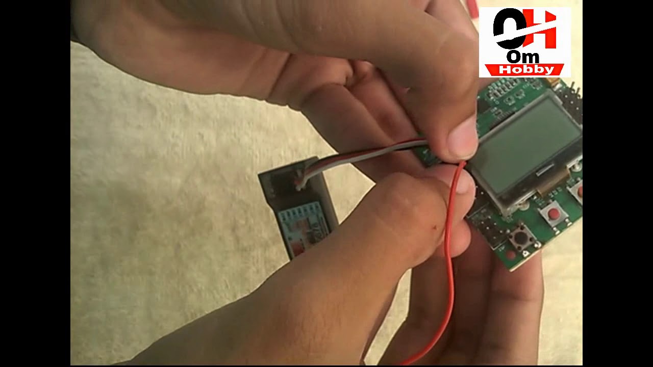
how to setup kk 2.1.5 flight controller board.
Hi guys in this video you will learn all thing about the Setup Of KK
2.1.5 Flight Controller or How To Connect KK 2.1.5 Flight Controller so in this video i will do kk 2.1.5 flight controller setup mins all connection.
So guys lot of people asking me how to to do wiring of kk 2.1.5 flight controller board so in think we should make a video on setup of kk 2.1.5 controller board as well as How To Program Flight Controller.
Quadcopter. flight,control, controller ,kk2.1.5, kk2, setup,set, beginner, start, good, flying, camera, gymbal, smartphone, easy, aeroplane, drone, diy, full, video, settings,pi gain ,pi limit,gain, limit, self level, reset, acc calibration, throttle, receiver test, fly, transmitter, arminig, arm, armed, how, to, flysky,simple
KK 2.1.5 Flight Controller Setup And Connection | Review Of KK 2.1.5 Flight Controller
how to setup kk 2.1.5 flight controller and connection | review of kk 2.1.5 flight controller
The next evolution of the rotor revolution is here!! The KK2.1.5 is packing new found power with updated sensors, memory and header pins.
The KK2.1.5 is next big evolution of the first generation KK flight control boards. The KK2.1.5 was engineered from the ground up to bring multi-rotor flight to everyone, not just the experts. The LCD screen and built in software makes install and setup easier than ever. A host of multi-rotor craft types are pre-installed, simply select your craft type, check motor layout/propeller direction, calibrate your ESCs and radio and you’re ready to go! All of which is done with easy to follow on screen prompts!
The original KK gyro system has been updated to an incredibly sensitive 6050 MPU system making this the most stable KK board ever and allowing for the addition of an auto-level function. At the heart of the KK2.1.5 is an Atmel Mega644PA 8-bit AVR RISC-based microcontroller with 64k of memory. An additional polarity protected header has been added for voltage detection, so no need for on-board soldering. A handy piezo buzzer is also included for audio warning when activating and deactivating the board.
The KK2.1.5 added polarity protection to the voltage sense header and a fuse protected buzzer outputs, in case something is accidentally plugged in incorrectly. The voltage sense line has been updated for better accuracy. The board is clearly labeled and the voltage sense line color has been changed to red for easy identification, making installation and connections a snap.
If you’re new to multi-rotor flight or have been unsure about how to setup a KK board then the KK2.1.5 was built for you. The 6 Pin USBasp AVR programming interface ensures future software updates will be quick and easy.
Specs:
Size: 50.5mm x 50.5mm x 12mm
Weight: 21 gram (Inc Piezo buzzer)
IC: Atmega644 PA
Gyro/Acc: 6050MPU InvenSense Inc.
Auto-level: Yes
Input Voltage: 4.8-6.0V
AVR interface: standard 6 pin.
Signal from Receiver: 1520us (5 channels)
Signal to ESC: 1520us
Firmware Version: 1.6:
Pre-installed firmware.
Dualcopter
Tricopter
Y6
Quadcopter +
Quadcopter X
Hexcopter +
Hexcopter X
Octocopter +
Octocopter X
X8 +
X8 X
H8
H6
V8
V6
Singlecopter 2M 2S
Singlecopter 1M 4S
The Mixer Editor allows you to adjust where and how much signal the motors receive from stick input and sensors. This allows you to create any configuration possible with up to 8 motors or servos.
The HobbyKing KK2.1.5 Multi-Rotor controller is a flight control board for multi-rotor aircraft (Tricopters, Quadcopters, Hexcopters etc). Its purpose is to stabilize the aircraft during flight. To do this it takes the signal from the 6050MPU gyro/acc (roll, pitch and yaw) then passes the signal to the Atmega644PA IC. The Atmega644PA IC unit then processes these signals according the users selected firmware and passes control signals to the installed Electronic Speed Controllers (ESCs). These signals instruct the ESCs to make fine adjustments to the motors rotational speed which in turn stabilizes your multi-rotor craft.
The KK2.1.5 Multi-Rotor control board also uses signals from your radio systems receiver (Rx) and passes these signals to the Atmega644PA IC via the aileron, elevator, throttle and rudder inputs. Once this information has been processed the IC will send varying signals to the ESCs which in turn adjust the rotational speed of each motor to induce controlled flight (up, down, backwards, forwards, left, right, yaw).


